 » Site Navigation » Site Navigation | | | | » Recent Threads | 1999 M3 Swap 09-07-2023 10:10 PM 06-01-2024 03:04 PM 7 Comments, 409,541 Views | | | My 318ti build 05-21-2024 04:48 PM 05-28-2024 06:42 PM 1 Comments, 3,295 Views | | | OMG!OMG! 05-28-2024 08:53 AM 05-28-2024 08:53 AM 0 Comments, 1,266 Views | |  |  |  | |  11-18-2008, 02:37 PM 11-18-2008, 02:37 PM | | | Senior Member Join Date: Dec 2007 Location: Gulfport, Florida Posts: 3,208 |  Air Pump Simulator DIY for $12.45 Air Pump Simulator DIY for $12.45
I have completed my final version of my air pump simulator and it passed the testing this morning with no error codes. All parts from Radio Shack and total cost $12.45. No more $150-$200 to buy these online. I will post the complete DIY this evening when I get home from work. Here's a picture of... |  |  | | |
Quote: Originally Posted by covert24  Alright. Now. To test it, you just put the O2 and DME wire together on one lead Of the Multimeter and then the other lead of the M/M on the GND/Negative from the SAP wire and look for .200 volts? Then disconnect SAP +\- and then what should I put the M/M on to see if it's straight through? I'm sorry my brain has been taxed beyond it's limits between trying to figure out this SAP sim and INPA/Ediabas. Mostly INPA.....
Edit: I also forgot to mention how much I appreiate all the help so far from both of you. Also what kind of decoupling capacitor would you recommend me to get and which to components would you put in inline with? Im seriously considering ordering a Pre-printed board if my hack job doesn't work :/ | No to test energize the sim and test the DME wire only to ground. You should have 200mv or around there. When the simulator has no power or is off the O2 and DME wire should be ohm'ed and be a dead short. The reason is to install you cut the O2 signal wire and patch the simulator in. When the Sim is off the O2 signal is sent to the DMEsince the simulator is in pass-though and the O2 signal is sent like the wire was never cut.. When the DME calls for Air Pump the sim goes active and cut the O2 reading and sends a 200mv signal to trick the DME into thinking the air pump is in and working correctly. Hope this clears it up a little | | | | |
Quote: Originally Posted by covert24 ... what kind of decoupling capacitor would you recommend me to get and which to components would you put in inline with? | The datasheet (728K PDF) states that an 0.33µF (or more) capacitor is required between input and ground if the regulator is an appreciable distance from the power supply filter (most likely). It also recommends an 0.1µF capacitor between the output and ground for better stability. Quote: | Im seriously considering ordering a Pre-printed board if my hack job doesn't work :/ | I've been quite happy with these guys for small, one off boards. They are a bunch of hobby robotics enthusiasts who arrange group PCB orders for their projects. | | Last edited by John Firestone; 09-12-2011 at 09:20 AM.. | | |
Quote: Originally Posted by xxxJohnBoyxxx No to test energize the sim and test the DME wire only to ground. You should have 200mv or around there. When the simulator has no power or is off the O2 and DME wire should be ohm'ed and be a dead short.
The reason is to install you cut the O2 signal wire and patch the simulator in. When the Sim is off the O2 signal is sent to the DMEsince the simulator is in pass-though and the O2 signal is sent like the wire was never cut.. When the DME calls for Air Pump the sim goes active and cut the O2 reading and sends a 200mv signal to trick the DME into thinking the air pump is in and working correctly. Hope this clears it up a little | Wow I'm an idiot lol. I've read and re-read this entire thread and it didn't click until you posted that. Thank you! I will test it when I get out of work and report back with my results. Quote: Originally Posted by John Firestone The datasheet (728K PDF) states that an 0.33µF (or more) capacitor is required between input and ground if the regulator is an appreciable distance from the power supply filter (most likely). It also recommends an 0.1µF capacitor between the output and ground for better stability. I've been quite happy with these guys for small, one off boards. They are a bunch of hobby robotics enthusiasts who arrange group PCB orders for their projects. | Alright well looking at radioshak they only have a 1.0uf for the input to ground and they have a .1uf for the output to ground. Would these be sufficient given there voltage is a little high or is that just the maximum voltage they can handle? Links: Input-Ground: http://m.radioshack.com/radioshack/p...egoryId=&path= Output-Ground: http://m.radioshack.com/radioshack/p...egoryId=&path= Would these be sufficient? | | | | |
The 50V is the maximum rated working voltage. The ceramic capacitor may behave a little differently depending on voltage, but that won't affect its use here. I would not put a tantalum capacitor on the voltage regulator input. They are notorious sensitive to low impedance voltage changes, and usually fail by shorting out.  How much trouble would it be to wire three 0.1µF ceramic capacitors in parallel? | | Last edited by John Firestone; 09-12-2011 at 07:40 PM.. | | |
Alright update: I feel like I wanna jab this soldering iron into my temple...
It's not working and I'm not sure why. Everything is soldered on correctly and the relays click when they are energized but no dice on the voltage deal.
I mean I get voltage from the DME wire but when I turn the pots nothing happens with the readings. And this is my second set if pots by the way. Any specific tests I could do to make sure each component (other then the relays) is working correctly? Going to try and wake up a little early this morning and see if I can make any headway before work. Maybe I can go to work happy lol. Realized today I had the +/- leads on my meter switched btw.... Yea it's been a little bit of a struggle.. Haha | | | | |
Oh was browsing the other threads on this topic and was wondering if there is a shematic out using a DPDT relay instead of two singles. Just curious as that would probably be easier to wire up.. I think.. | | | | |
Ok I just tested the regulator and it's output and ground are reading 0 ohms and the input is reading what it should be (12 or so volts). Does this mean my regulator is bad? I was able to get around 480mV on the DME wire but turning the pots only brought it down to around 430mV. What gives?! | | | | |
Quote: Originally Posted by covert24 Ok I just tested the regulator and it's output and ground are reading 0 ohms and the input is reading what it should be (12 or so volts). Does this mean my regulator is bad? I was able to get around 480mV on the DME wire but turning the pots only brought it down to around 430mV. What gives?! | Is your regulator padding the voltage to 5 volts? Also did you use the correct pots? Pots center is voltage then outside two are padded voltage to get you down to 200mv | | | | |
The regulator isn't outputting anything and the pots are indeed correct I got angry and threw it on the ground and broke the board in half.... So needless to say I ordered the the pre made board of of batchpcb and will be getting all new components... How long should I make the wires btw? Any certain length I should shoot for? | | | | |
mouser.com or digikey.com are good sources for component parts. And boards, project boxes...etc... | | | | |
Quote: Originally Posted by covert24 The regulator isn't outputting anything and the pots are indeed correct I got angry and threw it on the ground and broke the board in half.... So needless to say I ordered the the pre made board of of batchpcb and will be getting all new components... How long should I make the wires btw? Any certain length I should shoot for? | I install my simulator in the cabin since they are not weather resistant. Wires need to be long enogh to reach both O2 sensor signal wires and power wires need to be long enough to reach the air pump plug so it is powered by the DME calling for air pump at the plug. I do about 7 feet of wire on each connection and cut off what I don't need. You can also tap directly into the DME wiring harness for a shorter wire solution however it is not fun tearing apart the wiring harness and you need the DME diagram pinout for your cars year & model to ensure you are tapping the correct wires. John Smith | | | | |
Quote: Originally Posted by xxxJohnBoyxxx I install my simulator in the cabin since they are not weather resistant.
Wires need to be long enogh to reach both O2 sensor signal wires and power wires need to be long enough to reach the air pump plug so it is powered by the DME calling for air pump at the plug. I do about 7 feet of wire on each connection and cut off what I don't need.
You can also tap directly into the DME wiring harness for a shorter wire solution however it is not fun tearing apart the wiring harness and you need the DME diagram pinout for your cars year & model to ensure you are tapping the correct wires.
John Smith | Well I ordered the batchpcb board nOt realizing it takes about a month to get it....... Huge let down... Anyway, what gauge wire would you recommend for this thing. I want it to be functional but not have too thin/thick wires running all in the engine bay. I was thinking of maybe putting the box under one of the cabin filter housings since I wouldn't know where to begin or where to put it if I were to route it to the inside of the car. | | | | |
Quote: Originally Posted by covert24 Anyway, what gauge wire would you recommend for this thing. I want it to be functional but not have too thin/thick wires running all in the engine bay.... | The ETM shows those circuits wired with 0.5 mm^2 which translates to 20 AWG. I would probably use 18 AWG if you can't find 20, especially for the 12V wire. It is on an unfused circuit, save an upstream power relay. At least then you would not be sinning quite as badly as BMW. You could use 22 for the other wires if you are careful how you strip and lay them. (I have seen 18 being the smallest gauge recommended for the shade tree mechanic, but then some may strip wire with a knife blade or their teeth.) | | Last edited by John Firestone; 09-14-2011 at 10:20 AM.. | | | 
Quote: Originally Posted by John Firestone The ETM shows those circuits wired with 0.5 mm^2 which translates to 20 AWG.
I would probably use 18 AWG if you can't find 20, especially for the 12V wire. It is on an unfused circuit, save an upstream power relay. At least then you would not be sinning quite as badly as BMW. You could use 22 for the other wires if you are careful how you strip and lay them. (I have seen 18 being the smallest gauge recommended for the shade tree mechanic, but then some may strip wire with a knife blade or their teeth.) | Alrighty awesome thank you! So 18awg wires for the "power" and I'll use 20 for the DME/O2 wires just to be on the safe side. I just went to the dentist yesterday so stripping wires my teeth is a no no. I have a wire cutter/stripper that I use for all of my electronic projects so I have no reason not to use it. You guys have been a tremendous help thus far and I can't thank you enough. Im sorry I couldn't get the DIY version working. Mixture of bad components and frustration is what did me in. Once I receive the batchpcb board I will give you guys an update and what's going on. Thanks again! | | | | |
Wow. All these grateful waves -- you deserve to succeed.  Here is a snapshot of some parts that are going into my car: to improve the DRLs and to add puddle lights and BMW-style pathway lighting: 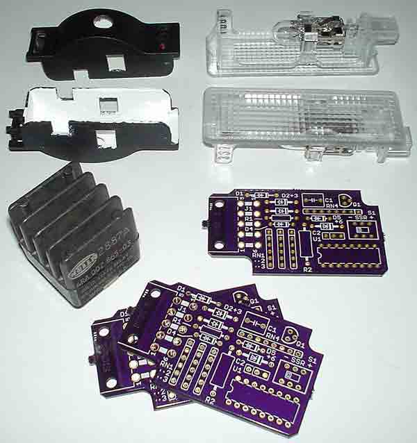 The purple circuit boards arrived this afternoon from dorkbotpdx, exactly three weeks after I sent in the design. It's my second try so that I can use the smaller, less expensive and more readily available solid state relay at their right. (The car only needs one board.) | | Last edited by John Firestone; 09-15-2011 at 06:58 PM.. | | |
| Currently Active Users Viewing This Tutorial: 1 (0 members and 1 guests) | | |
 Posting Rules Posting Rules | You may not post new threads You may not post replies You may not post attachments You may not edit your posts
HTML code is On
| | |
|


 Linear Mode
